


January 21, 2024
I. Understanding the BMW Next ICOM:
Before we dive into the diagnostic and programming process, let's familiarize ourselves with the BMW Next ICOM. The BMW Next ICOM is an advanced diagnostic tool that connects to your BMW's OBD-II port, providing access to various modules and systems. It is an essential tool for both professional mechanics and BMW enthusiasts who want to diagnose and program their vehicles.
II. Diagnosing Your BMW:
1. Connecting the BMW Next ICOM:
- Locate the OBD-II port in your BMW. It is usually found under the dashboard on the driver's side.
- Connect the BMW Next ICOM to the OBD-II port using the provided cable.
- Power on the BMW Next ICOM device.
2. Establishing Communication:
- Launch the diagnostic software on your computer or laptop.
- Connect your computer or laptop to the BMW Next ICOM device via a USB cable.
- Wait for the software to establish communication with the BMW Next ICOM.
3. Selecting the Appropriate Diagnostic Program:
- Once the communication is established, select the appropriate diagnostic program for your BMW model and year.
- The software will identify your BMW's VIN number and provide access to various diagnostic functions.
4. Running Diagnostics:
- Follow the on-screen prompts and select the desired diagnostic function.
- The BMW Next ICOM will scan your vehicle's modules and systems, providing real-time data, fault codes, and other relevant information.
- Analyze the diagnostic results and identify any issues or faults in your BMW.
III. Programming Your BMW:
1. Preparing for Programming:
- Ensure your BMW's battery is fully charged or connected to an external power source during the programming process.
- Close all unnecessary applications on your computer or laptop to avoid any interruptions.
2. Selecting the Programming Function:
- Launch the programming software on your computer or laptop.
- Connect your computer or laptop to the BMW Next ICOM device via a USB cable.
- Wait for the software to establish communication with the BMW Next ICOM.
3. Programming Process:
- Select the appropriate programming function based on your requirements (e.g., firmware updates, module replacements, coding changes).
- Follow the on-screen prompts and enter the necessary information.
- The BMW Next ICOM will guide you through the programming process, ensuring the correct data is written to your BMW's modules.
4. Verifying Programming Success:
- After the programming process is complete, run a final diagnostic scan to ensure all changes have been successfully implemented.
- Check for any error codes or issues that may have arisen during the programming process.
- Test the functionality of the programmed modules to ensure they are working as intended.
With the BMW Next ICOM diagnostic and programming tool, diagnosing and programming your BMW has become more accessible than ever. By following the step-by-step guide outlined in this blog post, you can effectively diagnose any issues and program your BMW according to your preferences. Remember to stay updated with the latest software and firmware releases to make the most out of your BMW Next ICOM device. Happy diagnosing and programming!
Posted by: Emily white at
02:21 AM
| No Comments
| Add Comment
Post contains 611 words, total size 4 kb.
January 11, 2024
1. Understanding the Cat Comm Adapter:
The Cat Comm Adapter is a diagnostic tool designed specifically for Caterpillar equipment. It acts as a communication link between the Electronic Control Modules (ECMs) of the machinery and the diagnostic software used by technicians. This adapter allows for real-time monitoring, troubleshooting, and programming of various parameters within the equipment.
2. Key Features and Functionality:
The Cat Comm Adapter offers an array of features that set it apart from traditional diagnostic tools. Some of its notable functionalities include:
a) Advanced Diagnostics: The adapter provides access to a wide range of diagnostic tests, enabling technicians to identify and resolve equipment issues swiftly.
b) Data Logging: It allows for the collection and analysis of critical operational data, aiding in preventive maintenance and improving machine performance.
c) Firmware Updates: The adapter supports the updating of ECM firmware, ensuring that the equipment is running on the latest software and optimized for efficiency.
d) Customization Options: With the Cat Comm Adapter, technicians can customize certain parameters of the ECMs to suit specific job requirements or environmental conditions.
3. Benefits of the Cat Comm Adapter:
The Cat Comm Adapter brings several benefits to equipment owners, operators, and maintenance personnel:
a) Reduced Downtime: The real-time monitoring and advanced diagnostics capabilities of the adapter enable swift identification and resolution of equipment issues, minimizing downtime.
b) Cost Savings: By promptly addressing potential problems, the adapter helps prevent major breakdowns and costly repairs, resulting in significant savings over time.
c) Improved Efficiency: The ability to analyze operational data allows for better decision-making, leading to increased equipment efficiency and optimized performance.
d) Enhanced Safety: With its ability to monitor critical parameters, the adapter contributes to a safer work environment by ensuring that equipment is operating within specified safety limits.
4. Applications and Industry Impact:
The Cat Comm Adapter finds extensive application in various industries that rely on heavy equipment. Construction, mining, agriculture, and transportation are just a few sectors that benefit from this cutting-edge technology. The adapter has transformed the way equipment is maintained, improving reliability, productivity, and overall operational efficiency.
In an industry where every minute counts, the Cat Comm Adapter has emerged as a game-changer. Its advanced diagnostic capabilities, real-time monitoring, and ability to optimize equipment performance make it an indispensable tool for heavy equipment owners and operators. With its numerous benefits and wide-ranging applications, the Cat Comm Adapter has revolutionized the field of heavy equipment diagnostics, paving the way for increased productivity and reduced downtime.
Posted by: Emily white at
03:03 PM
| No Comments
| Add Comment
Post contains 484 words, total size 4 kb.
August 07, 2023
 Holland Electronic Service Tools (CNH EST) is a full diagnostic tool for New Holland, Kobelco, CASE, Steyr, Flexicoil, FK, O&K equipment. This tool allows users to check parameters, retrieve faults, run diagnostic tests, make ECU and parameter programming, and view diagnostic procedures and schematics. It also includes E.A.S.y, an additional engine diagnostic and download tool.
Posted by: Emily white at
11:30 AM
| No Comments
| Add Comment
Post contains 801 words, total size 6 kb.
July 31, 2023
Posted by: Emily white at
02:31 AM
| No Comments
| Add Comment
Post contains 696 words, total size 5 kb.
July 22, 2023
Posted by: Emily white at
04:01 AM
| No Comments
| Add Comment
Post contains 350 words, total size 3 kb.
July 19, 2023
Posted by: Emily white at
08:09 AM
| No Comments
| Add Comment
Post contains 762 words, total size 6 kb.
March 27, 2023

You must read the warnings and instructions which are contained in the safety section of this manual. Before you perform any operation or maintenance procedures ensure you understand the warnings and instructions.
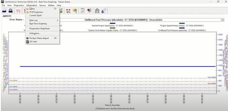
Caterpillar ET 2023A & 2019C Electronic Technician Diagnostic Software
Check Condition
1. Park the machine on level ground. Fully retract the boom and lower the boom.
2. Remove the cover from the rear of the chassis.
3. A limited inspection of the chains can be made through the rear of the boom. The boom extension chain can be inspected by fully extending the boom and looking on top of the intermediate section. If the chains are corroded, the chains must be removed from the boom for cleaning and a full inspection. If the chains require lubricant, the chains must be removed from the boom for cleaning and a full inspection. Refer to the Hydraulic System Systems Operation, Testing and Adjusting, "Boom Chain – Clean/Inspect/Lubricate”or consult your Caterpillar dealer
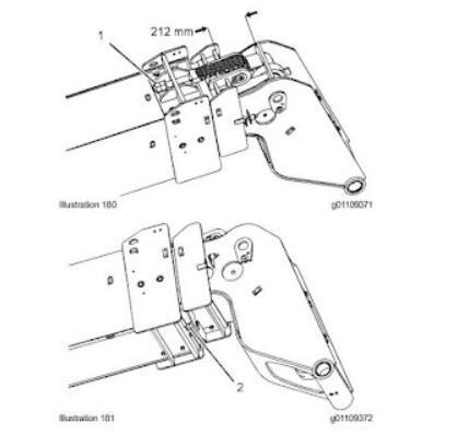
4. Set the minimum distance to 224 mm (8.8 inch) between boom section 2 and boom section 3. The maximum allowable distance is 234 mm (9.2 inch). Tighten extension chain (1) in order to move section 3 outward. Tighten retraction chain (2) in order to move section 3 inward. If the distance is significantly more than 224 mm (8.8 inch), slacken both chains and refer to Step 1.
5. After setting the distance to the required tolerance, tighten the extension chain to 20 N-m (15 lb ft).
6. Tighten the retraction chain to 18 N-m (13 lb ft).
7. Tighten the extension chain to 105 ± 5 Nm (77 ± 4 lb ft).
8. Tighten the retraction chain to 70 ± 5 Nm (52 ± 4 lb ft).
9. Extend the boom and retract the boom several times. Check the torque for the extension chain. Check the torque for the retraction chain.
10. Install the locknut for the extension chain. Torque the locknut for the extension chain to 105 ± 5 Nm (77 ± 4 lb ft).
10.2021 Caterpillar SIS EPC+Service Manual download & Full Installation Service
11. Install the locknut for the retraction chain. Torque the locknut for the retraction chain to 70 ± 5 Nm (52 ±
4 lb ft).
12. Check the shackles on both chains. If necessary, adjust the shackles in order to set the shackles horizontally.
13. Remove the stand and lower the boom.
Posted by: Emily white at
02:40 AM
| No Comments
| Add Comment
Post contains 423 words, total size 4 kb.
March 20, 2023

Now there are two models of theGM MDI 2the market ,One is copy cheaper, another one is original expensive.
1: GM MDI 2 Diagnostic Tool Multiple Diagnostic Interface this model is copy cheaper, if you need this model you can choose you need wifi or not. If you need the wifi. Pls note, the wifi we have put it on the mother board, there is no other extra wifi card to provide. If you choose the wifi,but when you run it, you do not know how to connect with the wifi, attached the setup video for your reference, you can setup the wifi according the video.
Function :
MDI scan tool is the Multi Diagnostics Interface
Works as the high-quality Vauxhall / Opel dealer diagnostic interface
Can be used with Global TIS, GDS 2, Tech2Win software on a new laptop
Provides full dealer level diagnostics and programming
Supports all Vauxhall /Opel 16 pin vehicles from 1996 to 2022
Perfoms quickly and used easily to make customers happy and win new business by offering the exact same functions as the main dealers, including:
* Automatic vehicle recognition
* DTC reading and removal
* Complete list of live data streaming for all main ECU
* Recordable / playback of live data
* New software flash for existing ECU to fix drivability issues
* Programming and installation of new ECU (PCM, ABS, Instrument cluster, air bag, fuel pumps etc.,)
* Programming new keys
* Setting / removing speed limiters
* J2534 pass thru offering ECU re-flash and diagnostics for other vehicle manufacturers, when subscribed to their specified software
* More dealer specific functions
2: Some customer said theGM MDI 2 with wifi. There is sperately wifi card like below picture.
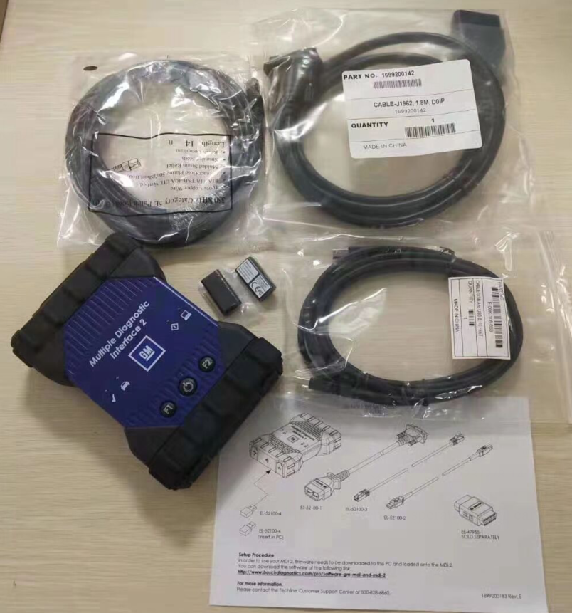
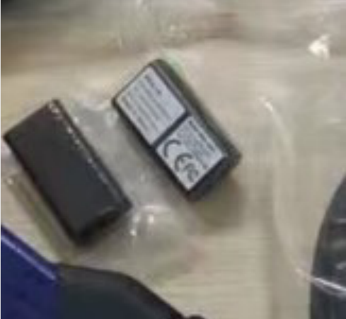
Yes, We have this model, this model is expensive original, just the wifi card need 300usd.the copy one with the wifi without the wifi card, have set the wifi on the motherboard. How to setup the wifi,we have attached the video before.
Fuction:
* Automatic vehicle recognition
* DTC reading and removal
* Complete list of live data streaming for all main ECU
* Recordable/playback of live data
* New software flash for existing ECU to fix drivability issues
* Programming and installation of new ECU (PCM, ABS, Instrument cluster, airbag, fuel pumps etc.,)
* Programming new keys
* Setting / removing speed limiters
* J2534 pass-thru ECU re-flash and diagnostics for other vehicle manufacturers, when subscribed to their specified software
* More dealer specific functions
If you need learn more, you can contact with us sales@obd2tool.com or you can search on our store:https://www.obd2tool.com
Posted by: Emily white at
03:07 AM
| No Comments
| Add Comment
Post contains 437 words, total size 5 kb.
March 09, 2023

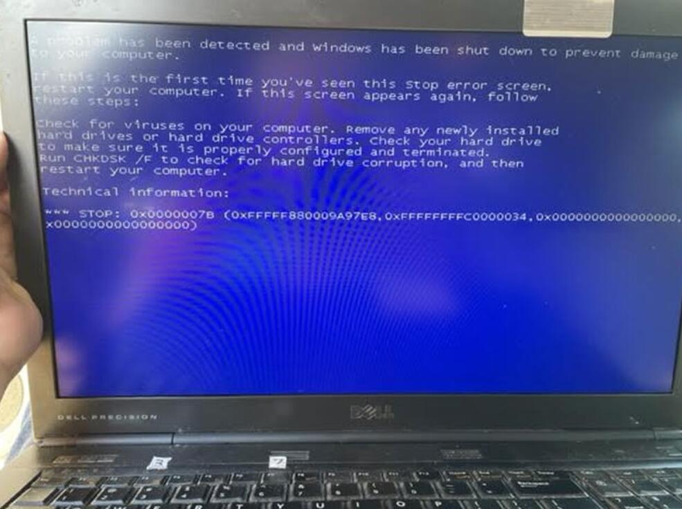
Recently, some customers gave feedbacks that it turned to blue screen when useGM MDIGDS tech2 Win software HDD. Screen as below:
"A problem has been detected and windows has been shut down to prevent damage to your computer.”
"Check for viruses on your computer. Remove any newly installed hard drives or hard controller. Check your hard drive to make sure it is properly configured and terminated. Run CHKDSK/ F to check for hard drive corruption, and then restart your computer.”
Technical information:
STOP: 0x0000007B(0xFFFFF880009A97E8. 0xFFFFFFFFC0000034. 0x0000000000000000. 0x0000000000000000)
Reason 1
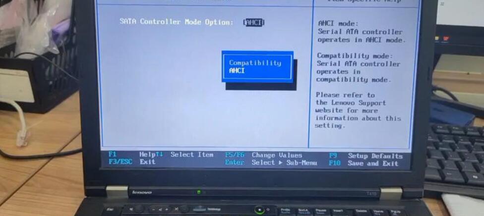
The reason to cause the problem is because of incorrect HDD format. Through changing Hard Disk Format to AHCI in bios can solve it.
How to change hard disk format to AHCI?
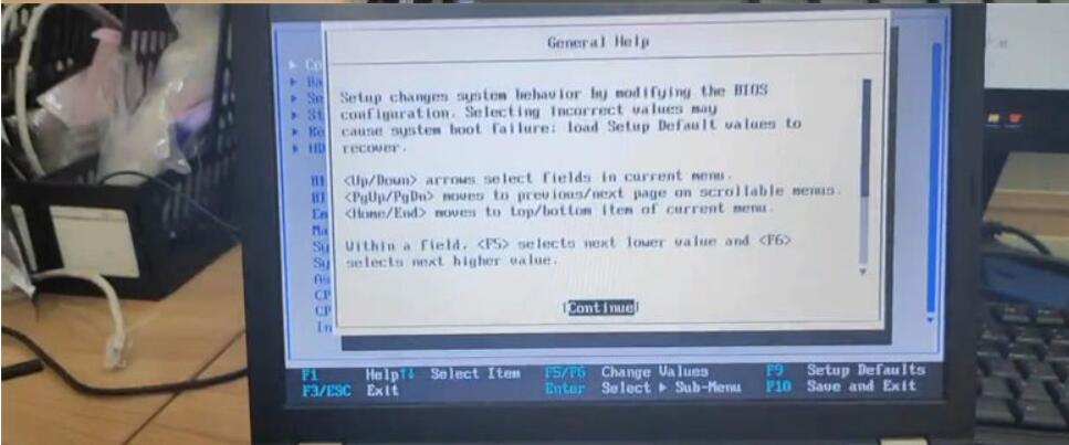
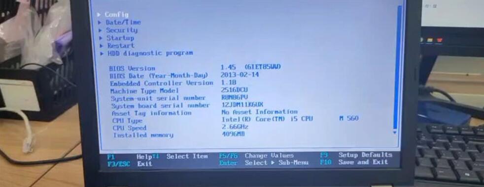
Step1. Restart computer, continuous press F1/F4/F12 button to access bios version.
(*Different computers may need to press different buttons. )
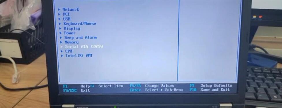
Step2. Continue >> Config >> Serial ATA(SATA) >> SATA Controller Mode Option: AHCI >> Change value to AHCI

Reason 2
GM MDI GDS Tech2 Used for pass-through programming and uses J2534 to provide faster programming speed. Depending on the vehicle’s structure, MDI’s communication speed is 20% to 70% faster than Tech 2.
Solution Program
But The compatibility of this GM MDI HDD is not very strong, so it may cause blue screen error when booting.
Please use the computer with the following requirements:
1.CPU: Intel
2.The computer should not be too old.Configuration Computer system requirements is best : 4GB RAM after 2008.
3 Please make sure your computer supports Win7 64-bit system.
4.The second hand D630 cannot be used with this HDD.
5 The computer format: AHCI :If the computer fails to boot, please enter the BOIS system and change the SATA driver to AHCI. Package includes: 1 x 500GBGM MDI 22.5-inch SATA HDD.
How to install Tech2Win on Windows 7 or XP:
1. Run Tech2Win \ AutoInstall.exe and everything will be done.
2. Install VX Manager.
3. Open VX Manager and install the GM driver.
How to installGDS 2with VMWare:
1. Install VMware-player-6.0.6-2700073.exe
2. copy GDS2 VM to harddisk.
3. open GDS2 VM with VMware Playe
If you want to know more aboutGM Scanner, please visithttps://www.obd2tool.com
Posted by: Emily white at
01:50 PM
| No Comments
| Add Comment
Post contains 365 words, total size 7 kb.
February 28, 2023
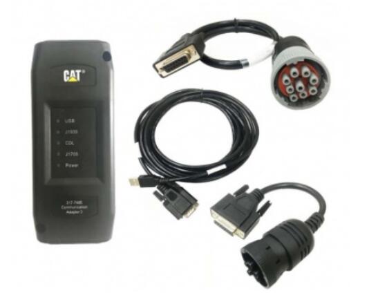
Caterpillar Comm Adapter III – diagnostic scanner interface is a cat group dealer workshop diagnostic tool built to work with Caterpillar heavy vehicles and Caterpillar engines. It is the latest generation of the cat Communication Adapter group and replaces the cat Comm Adapter II & the old 466-6258 and 317-7487 tool number.
Caterpillar scan tool includes:
CAT Comm Adapter III (part # 317-7485)
CD with the drivers
USB Cable (From device to your computer)
J1939/J1708 Cable (from device to your truck)
Hard Shell Case with foam inserts
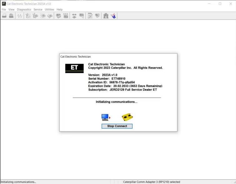
Caterpillar ET 2023A
Caterpillar Electronic Technician (Cat ET) is a service tool designed to run on a personal computer (PC) under Microsoft Windows. It will communicate with the Electronic Control Modules (ECMs) through a communication data link thus allowing you to diagnose existing and potential problems, configure the product and obtain data for analysis.
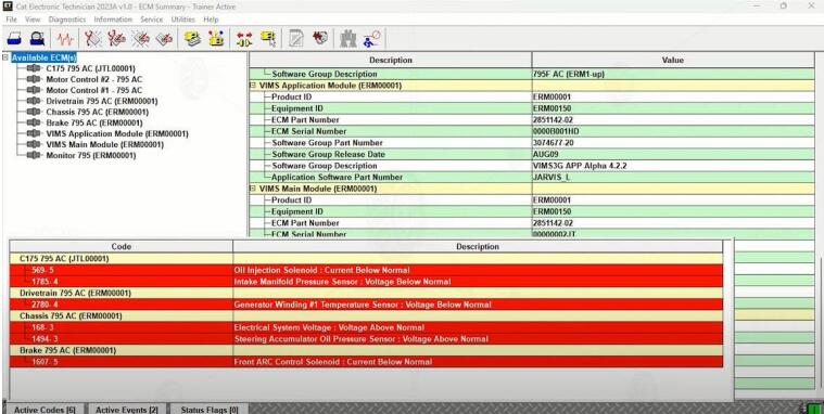
With the CAT Diagnostic Tool, you can:
View active and logged diagnostics
View events where irregularities occurred and were logged by the ECM
View the status of a group of parameters (temperatures, pressures, etc.) simultaneously
Record and log performance data
Graph a group of status parameters
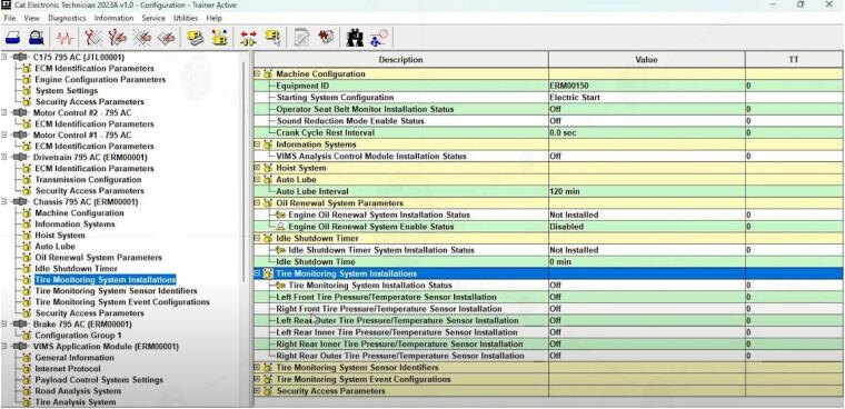
View the current configuration of an ECM
Change ECM configurations
Perform diagnostic tests
Perform calibrations
Print reports and diagnostic results
For some machine and engine products, additional functionality has been included with the service tool program
Caterpillar ET 2023A (replaces CAT ET 2022A, 2021A,2019C) Electronic Technician Diagnostic Software
Brand: Caterpillar
Region: WorldWide
Language: English, Chinese, Danish, French, German, Italian, Japanese, Portuguese, Russian, Spanish
Compatible OS: Windows 7 32 bit, Windows 7 64 bit, Windows 8/8.1 32 bit, Windows 8/8.1 64 bit, Windows 10 32 bit, Windows 10 64 bit
Publication date: 03.2023 year
Latest Caterpillar ET 2023A Software to work with CAT/CAT3 Truck Scanner
With one free activation, can send software online
PC, Communication Hardware, and Cable Requirements
To run the service tool, the next PC, communication hardware, and cable requirements must be met. NOTE: The minimum PC Configurations should not be used as a standard when buying new personal computers for service tool purposes. If the existing equipment meets these minimum requirements, it will run the service tool.
PC Requirements
Recommended Configurations
PC containing a 2.0 GHz dual-core processor
3GB RAM
3GB of the available hard disk drive
DVD-ROM drive (optionally)
15.4-inch XGA Screen (1280×1024 compatible)
Microsoft Windows™ 7 Professional or Windows 8 Professional, Windows 10 Professional (Not tested with Home Edition) (Note: Windows 8 RT is not supported)
RS232 port with 16550AF UART or compatible (for use with Comm Adapter II)
USB 1.1 or 2.0 port (for use with Comm Adapter 3)
Ethernet RJ45 connector
Built-in pointing device or mouse
For security purposes, Microsoft Internet Explorer version 11 or newer or Microsoft Edge is recommended.
Note: The most recent version of Microsoft Internet Explorer may not be validated to work with the service tool.
Caterpillar electronic technician 2021A with WinFlash future is an updated version of the caterpillar dealer diagnostic software that can help technicians to diagnose existing and potential problems with their electronically controlled Caterpillar Engines and Machines.
To get the vehicle information the Cat ET software must be connected to the Electronic Control Module (ECM). For this purpose, you need a suitable diagnostic link adapter (DLA), for instance, Genuine CAT Comm Adapter III .
The laptops with ARM CPUs (Snapdragon 8cx, Microsft SQ1, etc) type are not supported!
Microsoft ended extended support for Windows 7 as of January 2020. The CAT ET service tool no longer supports Windows 7 as of the 2020B release. The installation is still possible, but we’re not able to guarantee the stable work of 2020B or later versions.
The list of supported CAT machines and engines can be found below:
Engines:
Electric Power
Electric Power Generation
Industrial
Marine Power Systems
Oil and Gas
Machines:
Articulated Trucks
Asphalt Pavers
Backhoe Loaders
Cold Planers
Compactors
Dozers
Drills
Excavators
Feller Bunchers
Forest Machines
Forwarders
Harvesters
Hydraulic Mining Shovels
Knuckleboom Loaders
Material Handlers
Motor Graders
Off-Highway Trucks
Pipelayers
Road Reclaimers
Site Prep Tractors
Skid Steer and Compact Track Loaders
Skidders
Telehandlers
Track Loaders
Underground – Hard Rock
Underground – Longwall
Underground – Room and Pillar
Utility Vehicles
Wheel Dozers
Wheel Excavators
Wheel Loaders
Wheel Tractor-Scrapers
What’s New – 2022A
Microsoft® Windows™ 11 Compatibility
Service tool testing has been performed and the service tool is compatible with Windows 11.
ECM File Replacement Compare Feature
The service tool now has an ECM Replacement File Compare feature for troubleshooting purposes. This feature allows the user to compare one ECM replacement file with another from within the ECM Replacement feature screen. The feature will highlight the differences between the selected files as a whole or the user may select the "only show differences” checkbox.
Configuration Group Headings on ECM Replacement Feature
In order to help the user find ECM replacement configuration items easier, configuration items in the ECM Replacement, Fleet Configuration, and Product ECM features are now grouped under their group sub-headings, as is done in the main configuration feature.
What’s New – 2021A
No significant new features or feature enhancements
What’s New – 2020C
No significant new features or feature enhancements
What’s New – 2020B
Trainer Update – 299D3
The 299D3 Skid Steer Loader has been added to the Trainer application.
What’s New – 2020A
Product Status Report Updates
The Product Status Report has been updated to include throttle configuration information.
Built-in Factory Password Generator
The experimental feature allows you to decode (18-Bit passwords not supported) factory passwords
What’s New – 2019C
Indication of Selected Communications Adapter
The service tool now displays the selected communications adapter when the service tool is disconnected. The adapter name is displayed in the status area at the bottom right of the service tool window.
End of Support for Windows 7
Microsoft is ending extended support for Windows 7 as of January 2020. The service tool will be ending support for Windows 7 as of the 2020A release.
What’s New – 2019B
Automatic Product Status Report (PSR) Upload
The service tool includes a new tool that automatically uploads Product Status Reports. The tool scans for newly generated Product Status Reports and uploads them when an internet connection is available. The default is that automatic report uploading is enabled. The Preferences dialog has an option to disable the tool.
What’s New – 2019A
ECM Naming Changes
Certain ECMs connect to the service tool over two data links at the same time. The service tool shows a message popup when the ECM is only detected on one link. The service tool has been changed to add the text **INCOMPLETE** in the ECM name when the connection is incomplete. Service tool features that display a connection icon also use a new icon for an incomplete connection.
What’s New – 2018C
No significant new features or feature enhancements
What’s New – 2018B
CEOS Fleet Configuration File TOP
A CEOS (Customer Electronic Option Selection) Fleet Configuration File can be created/modified for an engine using the Service Tool. This is available in connected and disconnected mode.
Error When Launching Service Tool
There is a Microsoft issue with upgrading libraries during an installation involving certain versions of the C++ redistributable. After a successful service tool installation, when trying to run the service tool for the first time, one of the following errors may occasionally appear: "The entry point could not be located in api-ms-win-crt-runtime” or "The program can’t start because mfc140u.dll is missing from your computer.” If either of these messages is displayed, please let us know and we will send you to step by step troubleshooting guide. This procedure requires administrator rights.
Service Tool License Corruption Issues with Windows 10 Updates
Windows 10 updates 1709 and 1803 will corrupt service tool licenses. Future Window 10 updates may do the same
If either of the license error messages is displayed, please let us know and we will send you to step by step troubleshooting guide.
What’s New – 2018A
Trainer Update – 988K XE Wheel Loader
The 988K XE Wheel Loader has been added to the Trainer application.
What’s New – 2017C
Preferences Option to Save a Product Status Report to PDF
The Preferences dialog for the Product Status Report has changed. The dialog contains a new checkbox to automatically save a Product Status Report as a PDF file when the report is created. The service tool will continue to automatically save Product Status Reports as an XML file.
What’s New – 2017B
Product Status Report Updates
The Product Status Report has been updated to include certain history features supported by the ECM, such as the after-treatment Regeneration History and the Service Test History.
Winflash Screen Update
The screen for the Winflash feature has been updated. A new Expand All button opens all sections of the screen to show all details for ECMs detected by WinFlash. A new Collapse All button hides all sections of the screen, except for header rows showing detected ECM names.
Communication Hardware
Caterpillar Communication Adapter III Kit
Configuring Cat Electronic Technician to use the Communication Adapter 3
For Cat Electronic Technician to work with the Communication Adapter 3, the settings must be changed to select the Communication Adapter 3 as the Communication Interface Device:
Step 1 Start Cat Electronic Technician.
Step 2 Click the Stop Connect button when it appears.
Step 3 Select the utility menu.
Step 4 Choose "Preferences > Modify…”.
Step 5 Select the Communications tab.
Step 6 Select Cat Comm Adapter 3 (RP1210) and click OK.
NOTE: Because a growing number of products require multiple data link service, the "Enable Dual Datalink Service” checkbox has been pre-selected.
Servicing ECMs on more than one data link requires this checkbox to be enabled.
Failure to do this will result in undetected ECMs and reduced functionality.
Original Factory Caterpillar ET3 Adapter III Compare With OEM Caterpillar ET Diagnostic Adpater III
1. Original Factory CAT ET can use once pluged, no need install the USB drive, the software can automatic realize it for ET3 Adapter, and the machine can automatic weld the high quality Circuit board, quality will be more reliable.
2. The OEM Caterpillar ET Diagnostic Adapter III need use USB Drive to install, and need choose the COM Port, and in the software ET also need choose ET2 then can be used.
Posted by: Emily white at
02:43 AM
| No Comments
| Add Comment
Post contains 1711 words, total size 15 kb.
February 18, 2023

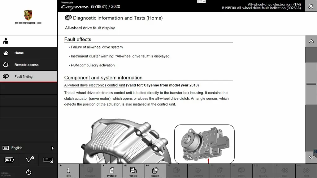
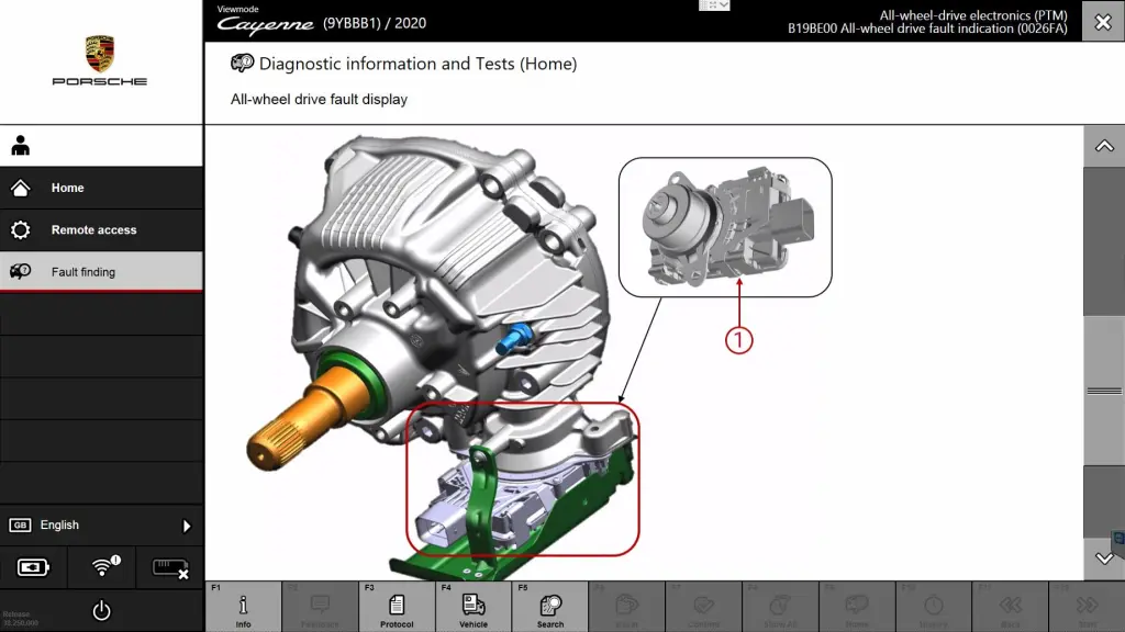
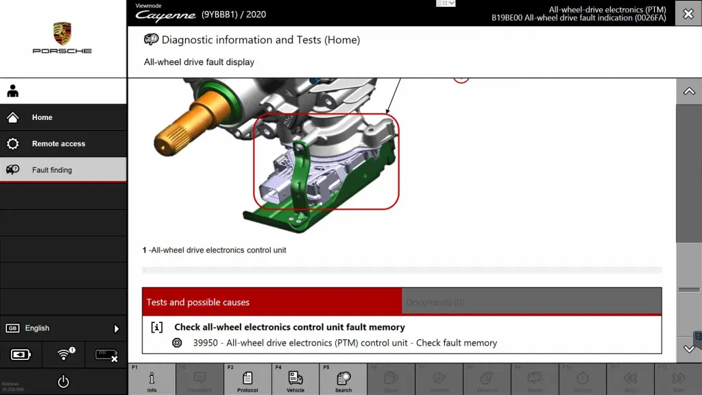
The Porsche PIWIS 3 (PST3) is the latest diagnostic tool on the market. It can read fault codes, clear fault codes, and display ECU information. It tests live data, displays actual values and programs. On all; Process malfunction navigation showing all internal circuit diagrams. Especially if produced after 2005. ThePIWIS IIIhas the original oscillometer and multimeter function. It’s the absolutely necessary tool for the job.
How to use the Porsche piwis 3 software to find a Porsche car faultrepair guide
1.Home-Diagnostics-Fault finding
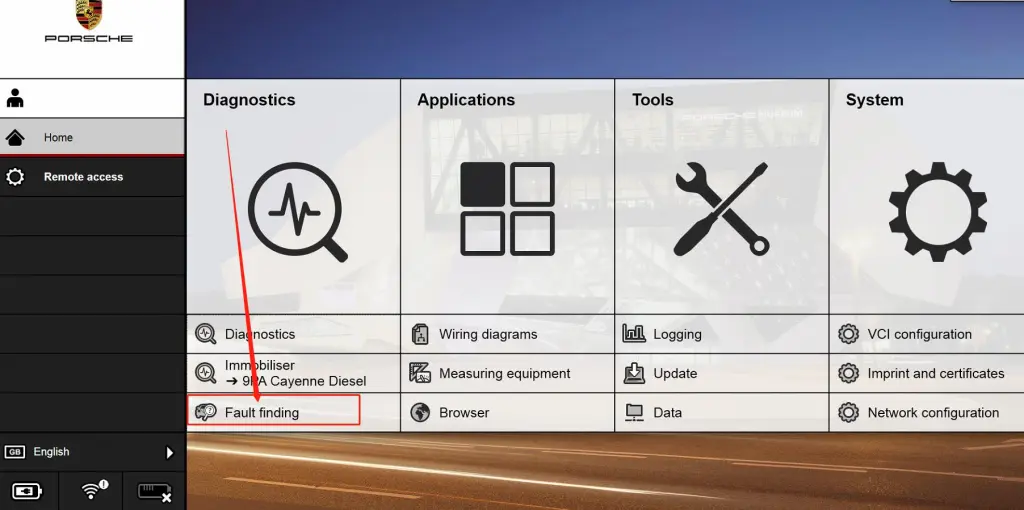

2.Model range-model year-mode type-control unit
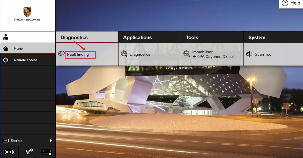
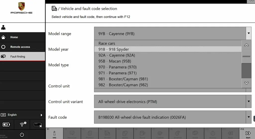
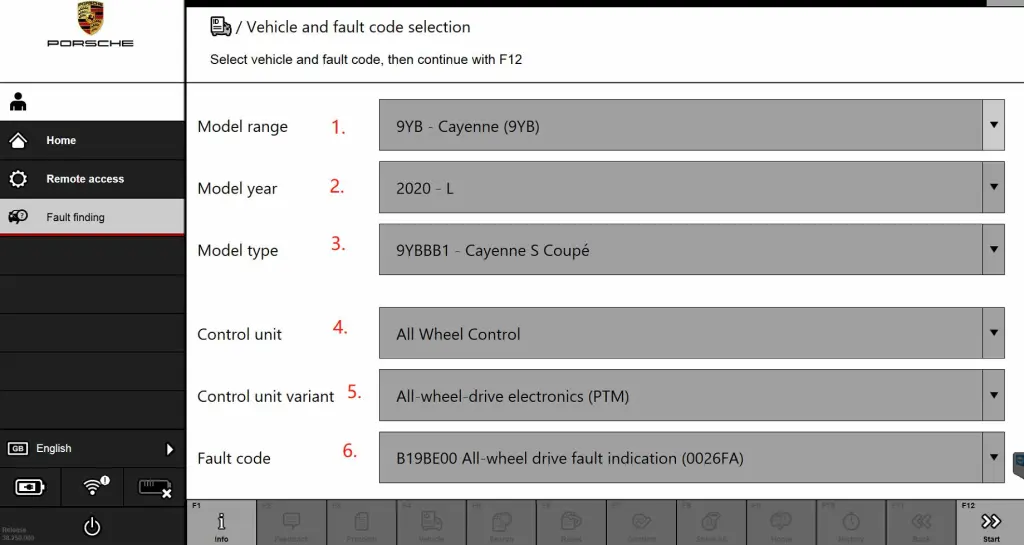
Hope it help
If you want to know more aboutPorsche diagnostic tools, please visithttps://www.obd2tool.com
Posted by: Emily white at
04:37 AM
| No Comments
| Add Comment
Post contains 110 words, total size 8 kb.
February 13, 2023
BMW Diagnostic ToolBMW ICOM Next, ICOM NANO or VXDIAG VCX SE BMW ICOM? Check brief comparison below:
1. ICOM Nano
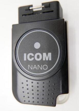
ICOM NANO is the new diagnostic unit for BMW. It’s wireless. Very small size.
Support E series with INPA, F series and G series diagnostic with E-sys.
Drawbacks:
Can’t connect to a hotspot like ICOM NEXT
Just available alone on a separate Wifi
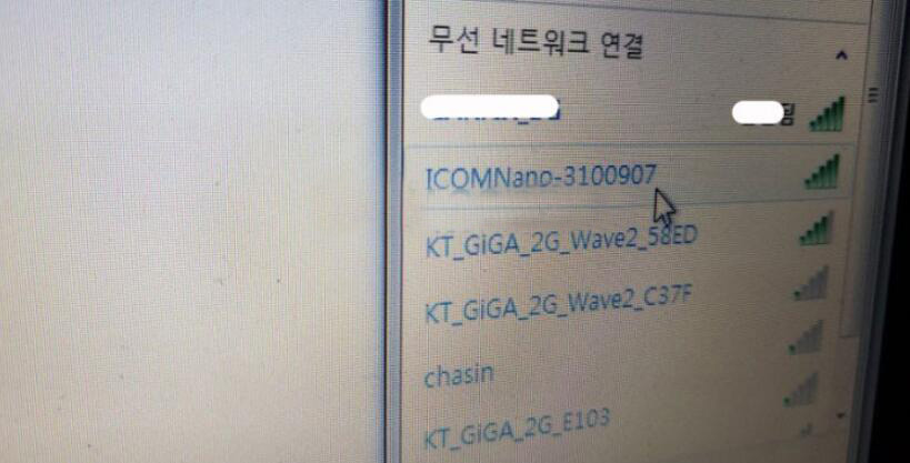
NcsExpert not connected
only for diagnosing, it risky for programming
F series is Only available for body coding.
After all, there was a reason why ICOM NEXT was expensive.
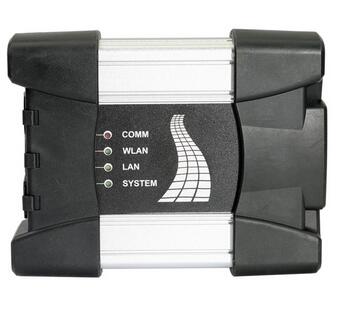
ICOM Next Benefits:
1. Wireless diagnosis connection
2. Ease of use in a shop with multiple active connections
3. Self-hosted DHCP server for ethernet programming
There are different ICOM next clone multiplexers on the aftermarket. All high-quality ICOM Next clones are discontinued due to a lack of chips. Only the ICOM Next using VXDIAG solution is available. So it is a VXDIAG BMW with ICOM Next case indeed. Let’s move to VXDIAG ICOM.

For those with the VCX DoIP:
No need for DHCP server or router, it’s build in.
– WiFi, LAN, USB, Type C to USB, DoNET remote multiple connection ways
– Firmware update is available via VXManager.
– For connection with ista-p you need to download BMW ptt driver from VXDiag, start Pass-Thru app in VXManager and emulate by loading dll. Make sure its set to SAEJ2534
– For connection with ista-d you need to set connect via icom/ethernet local network in ista settings.
If your license is valid you can also use cloud software
– For connection E-sys sometimes ZGW is not detected on first try, select connect via icom/ethernet tcp://<icom ip adress>:50160 than close connection. Now ZGW is available and connection can be made via vin or gateway url.
Posted by: Emily white at
02:32 AM
| No Comments
| Add Comment
Post contains 312 words, total size 5 kb.
January 30, 2023
How to Get BMW ECU Validation Service viaISTA BMWAfter Replacing Certain Control Modules
SITUATION
With the introduction of the new Headunit HU-H3 (MGU Media Graphics Unit), we have a new way protection mechanism against tampering.
If one or more of the following components MGU, TCB Telematic Communication Box (ATM-02), RSE Rear Seat Entertainment, or KOMBISP18 instrument cluster needs to be replaced the secure connection between them must be re-established. In order to re-establish the connection, an electronic certificate must be created from the BMW backend and imported into the Vehicle.
CAUSE
After the replacement of one of the mentioned Modules the Control Module needs a valid certificate in order to communicate with the other Modules.
CORRECTION
With the introduction of ISTA 4.14.1x, the Ecu validation service certificates can be created in manual steps.
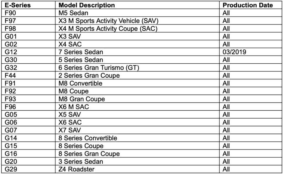
Models:
Step-by-Step Guidance for BMW ECU Validation Service By ISTA BMW
1. Go to "vehicle management” => "Control unit exchange”
2. Select the exchanged control unit in the "After ” tab and then calculate the measures plan. Then ISTA will automatically include the control unit validation in the measures plan.
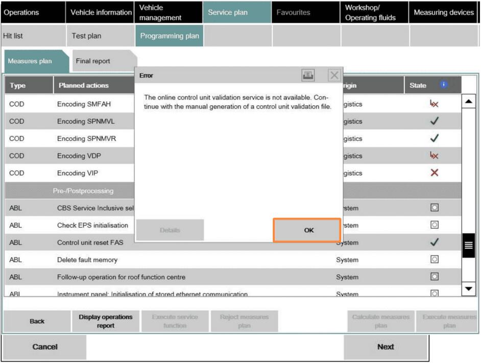
3. If ISTA cannot carry out automatic validation, a warning about the absence of control unit validation is displayed.
4. By clicking on the "Next” button, ISTA generates the required ValidationRequest_VIN_xxx.json file and opens a file dialogue to save it. The file needs to be stored and uploaded via DCSnet later.
5. ISTA displays a note confirming that the file was successfully saved. At this point, you can exit the process using the "Cancel” button. After processing the measures plan, the session can be closed.
6. Open DCSnet and select "ECU Validation Service” under "Service”. You can order the ECU validation service through us per VIN.
If the ECU Validation Service Menu is not showing up, please check your Access Roles in DEMS. If the ECU validation Service Role is missing, please contact your DEMS Administrator for getting access to it.
7. Upload the previously generated and downloaded ValidationRequest_VIN17_xxx.json file
8. The System checks the file, and after a few seconds, a new
ValidationRequest_VIN17_xxx_response.json file will be offered for downloading. This is
subsequently required by ISTA. Start a new ISTA session
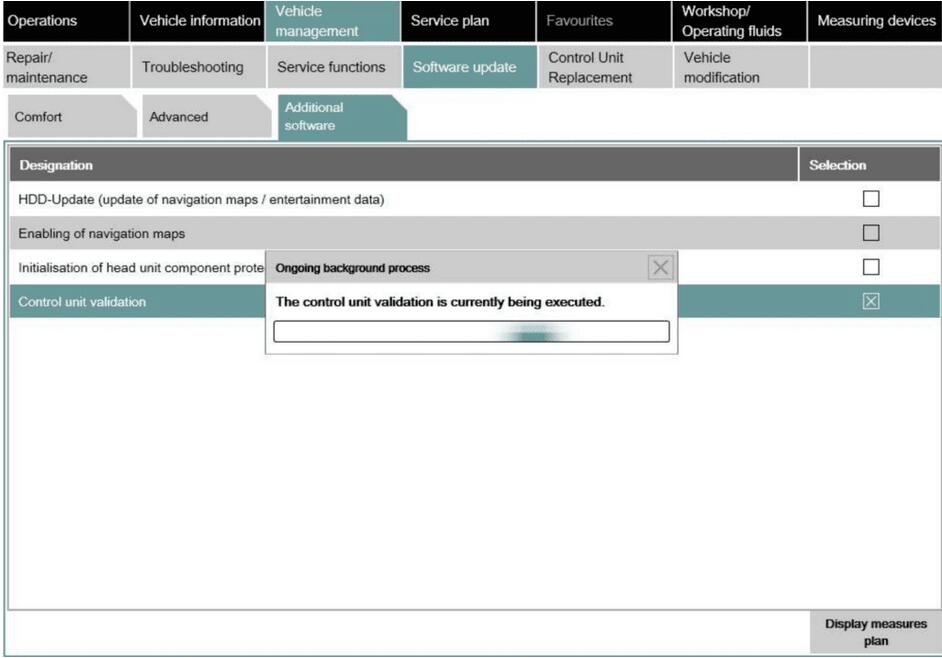
9. In order to import the JSON file, select "ECU Validation” in the "Additional Software” tab.
10. In order to import the validated file, select "Import control unit validation file manually” and confirm with "OK”.
11. Select the file ValidationRequest_VIN17_xxx_response.json in the file dialogue and confirm with "Continue”. (the file will be supplied by us if you ordered the ECU Validation Service from team autosvs.com)
12. The file is written into the vehicle and checked.
Ecu validation service Summary:
With the introduction of the new Headunit HU-H3 (MGU Media Graphics Unit), there is a new protection mechanism against tampering. If one or more of the following components needs to be replaced, the secure connection between them must be re-established:
• MGU TCB Telematic Communication Box (ATM-02);
• RSE Rear Seat Entertainment;
• KOMBISP18 instrument cluster.
Prior to re-establishing this connection, an Ecu validation service electronic certificate must be created in the BMW backend for importing into the Vehicle. After the replacement of one of the mentioned Modules, the Control Module needs a valid certificate for it to communicate with the other Modules. With the introduction of ISTA 4.14.1x, the BMW Ecu Validation Service certificates can be created either automatically, or alternatively in manual steps.
How to Get BMW ECU Validation Service viaISTA BMWAfter Replacing Certain Control Modules
SITUATION
With the introduction of the new Headunit HU-H3 (MGU Media Graphics Unit), we have a new way protection mechanism against tampering.
If one or more of the following components MGU, TCB Telematic Communication Box (ATM-02), RSE Rear Seat Entertainment, or KOMBISP18 instrument cluster needs to be replaced the secure connection between them must be re-established. In order to re-establish the connection, an electronic certificate must be created from the BMW backend and imported into the Vehicle.
CAUSE
After the replacement of one of the mentioned Modules the Control Module needs a valid certificate in order to communicate with the other Modules.
CORRECTION
With the introduction of ISTA 4.14.1x, the Ecu validation service certificates can be created in manual steps.
Models:
Step-by-Step Guidance for BMW ECU Validation Service By ISTA BMW
1. Go to "vehicle management” => "Control unit exchange”
2. Select the exchanged control unit in the "After ” tab and then calculate the measures plan. Then ISTA will automatically include the control unit validation in the measures plan.
3. If ISTA cannot carry out automatic validation, a warning about the absence of control unit validation is displayed.
4. By clicking on the "Next” button, ISTA generates the required ValidationRequest_VIN_xxx.json file and opens a file dialogue to save it. The file needs to be stored and uploaded via DCSnet later.
5. ISTA displays a note confirming that the file was successfully saved. At this point, you can exit the process using the "Cancel” button. After processing the measures plan, the session can be closed.
6. Open DCSnet and select "ECU Validation Service” under "Service”. You can order the ECU validation service through us per VIN.
If the ECU Validation Service Menu is not showing up, please check your Access Roles in DEMS. If the ECU validation Service Role is missing, please contact your DEMS Administrator for getting access to it.
7. Upload the previously generated and downloaded ValidationRequest_VIN17_xxx.json file
8. The System checks the file, and after a few seconds, a new
ValidationRequest_VIN17_xxx_response.json file will be offered for downloading. This is
subsequently required by ISTA. Start a new ISTA session
9. In order to import the JSON file, select "ECU Validation” in the "Additional Software” tab.
10. In order to import the validated file, select "Import control unit validation file manually” and confirm with "OK”.
11. Select the file ValidationRequest_VIN17_xxx_response.json in the file dialogue and confirm with "Continue”. (the file will be supplied by us if you ordered the ECU Validation Service from team autosvs.com)
12. The file is written into the vehicle and checked.
Ecu validation service Summary:
With the introduction of the new Headunit HU-H3 (MGU Media Graphics Unit), there is a new protection mechanism against tampering. If one or more of the following components needs to be replaced, the secure connection between them must be re-established:
• MGU TCB Telematic Communication Box (ATM-02);
• RSE Rear Seat Entertainment;
• KOMBISP18 instrument cluster.
Prior to re-establishing this connection, an Ecu validation service electronic certificate must be created in the BMW backend for importing into the Vehicle. After the replacement of one of the mentioned Modules, the Control Module needs a valid certificate for it to communicate with the other Modules. With the introduction of ISTA 4.14.1x, the BMW Ecu Validation Service certificates can be created either automatically, or alternatively in manual steps.
Posted by: Emily white at
03:00 AM
| No Comments
| Add Comment
Post contains 1714 words, total size 19 kb.
January 15, 2023
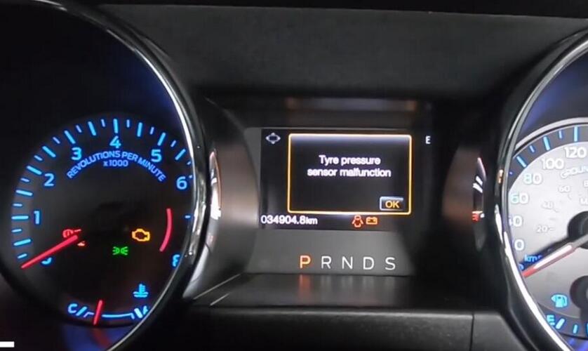
After TMPS sensors replacement,you will get error message "Tyre pressure sensor malfunction” on dashboard,now you need to perform TPMS sensor learning for your Ford Mustang.In this post car-auto-repair.com show you guide on how to useLaunch X431 deviceto do TPMS sensor learning.
Preparations:
Launch X431 PROS
Launch X431 TSGUNwith TPMS
Procedures:
Use Launch X431 Pro to perform a full diagnose for Ford Mustang
Trouble code found B124D

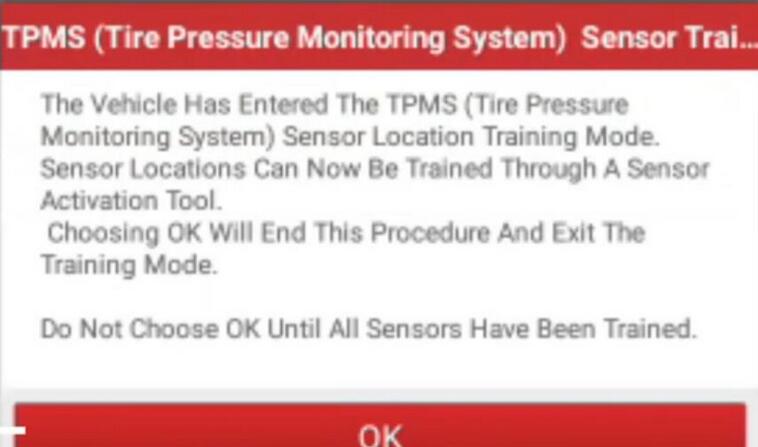
Go to special functions to select "TPMS sensor training mode”
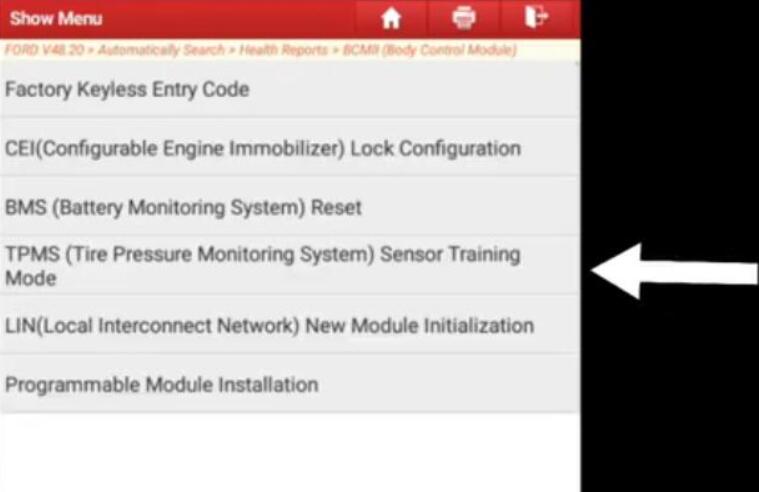
Car will horn while enter to training mode
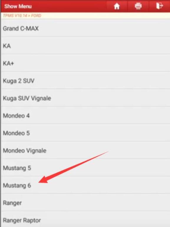
Select "TPMS” on Launch X431,select your car models
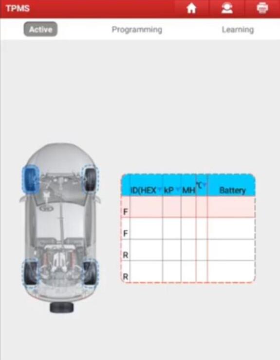
Use X431 TSGUN to do learning for 4 sensors
Car will horn while success learn the sensor
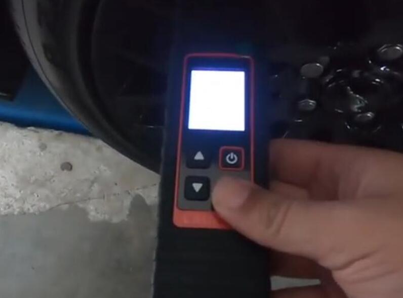
After all done make a test drive the sensors will work well.
More test report about Launch X431 please check:Launch X431 Test Report
Posted by: Emily white at
02:08 PM
| No Comments
| Add Comment
Post contains 143 words, total size 5 kb.
January 09, 2023

System and Hardware Requirements
Before you get things started, make sure that you’ve prepared the following:
1. ENET cable
2. E-sys software with EST token and pin
3. Psdzdata Lite version
4. Laptop with at least Windows 7 OS and 16 GB of available space
5. Coding Cheat Sheet for your vehicle model
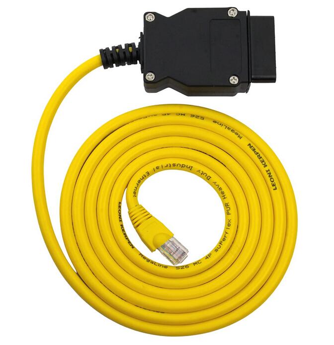
The ENET cable is built with an RJ45 connector on one side, that is used to connect with the ethernet port of your laptop computer, and a 16-pin connector on the other side for connecting to the OBD port of your vehicle. Make sure to get one with a shielded connector from a reliable seller. This will protect you from electrical noise interference and other connection interruptions that may affect the coding process.
What is BMW Esys

Commonly used functions of BMW E sys: ECU FLASH programming/code (one
ECU or more ECUs), FA, FSC browsing and editing, ECU file editing, ECU
function activation (need to use E sys launch pro or e sys plus), ECU
status, Vehicle integration level, navigation certificate status, etc.
BMW E sys can connect cars: BMW brand cars (BMW Mini, BMW Motors, Rolls Royce), F, G, I series
Connectivity for BMW E sys: BMW ICOM Next (recommended), ENET cable/ENET WIFI (recommended), BMW ICOM NANO, BMW ICOM A1 A2 A3.
Download and Install the E-sys Software
The E-sys software is mainly used for coding the BMW F Series , the new 1
Series, 3 Series, 5 Series, 7 Series , GT, and X3 models. Here’s how to
download and install E-sys:
1. Download the E-sys software for free here: E-sys Software Download
2. Extract the downloaded file using Winrar or with any similar extraction software.
3. Double click on the installation file, which is an exe file with a filename like "E-Sys_Setup_3_26_1_b42487.exe”.
4. Follow the default settings that will install E-sys to the recommended default location, shown as C:\EC-Apps\ESG\E-Sys.
5. Set the data path for E-sys. You can follow the recommended default location which is at C:\Data.
6. Click "Next” until the installation process starts. Then click "Finish” when the installation process is done.
How do I set up BMW ESYS?
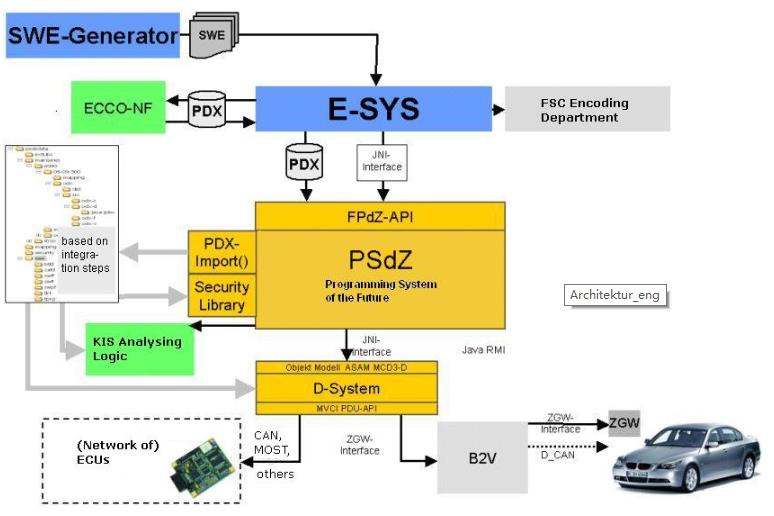
Schematic diagram of how BMW E-sys works
1. E sys Home;
2. E-sys selects the car series;
3. E-sys data setting;
4. E-sys Expert mode;
5. E-sys FA editor;
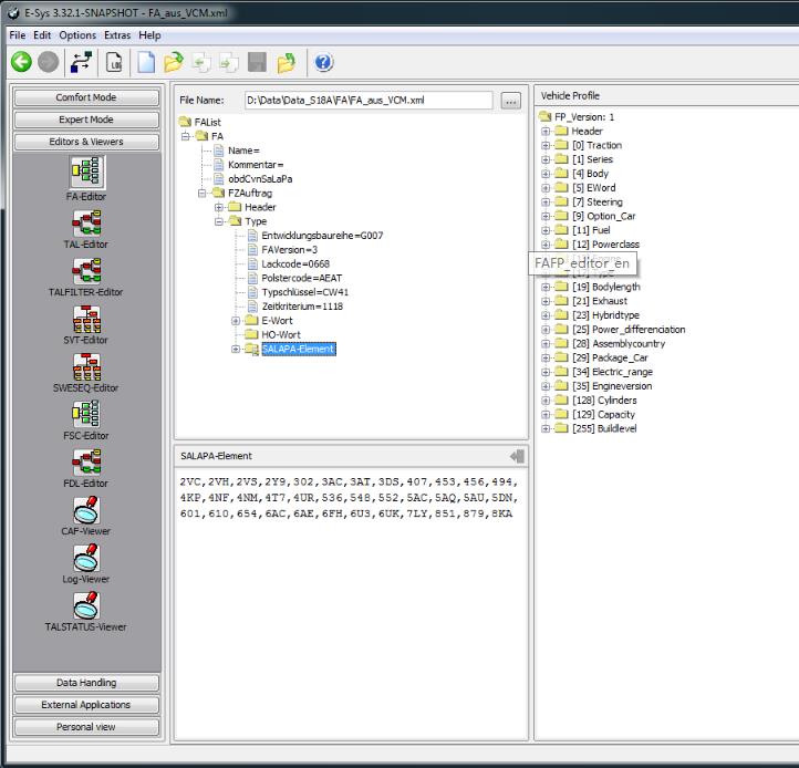
6. E-sys comfort Mode.
Download and Install Psdzdata
The Psdzdata contains all the data needed for BMW coding, flashing, and
firmware updates. Installing Psdzdata is an important final step in the
E-sys installation process. The E-sys software will be useless without
these essential data. Here’s how to download and install Psdzdata:
1. Psdzdata is available in two versions – the Full and the Lite
version. If you only want to do coding, Psdzdata Lite is recommended
because it will save you some space – approximately around 1GB compared
to 20GB of the Full version.
2. Extract the downloaded file using Winrar or with any similar
extraction software. You will find a new folder with the name "psdzdata”
after the extraction process.
3. Copy the "psdzdata” folder and paste it to the C:\Data location. This
will overwrite and replace the existing empty "psdzdata” folder in the
location with the extracted "psdzdata” folder that contains all the data
files that you need for BMW coding.
Coding Preparations
After you have successfully installed the software and tools that you
need for BMW coding, you need to prepare these things prior to the
actual coding process:
1. Before you proceed to code your BMW, you need to be familiar with and
sure of the things that you want to do with your vehicle. Do not
proceed if you are unsure of what to do. Do not attempt to skip or guess
the essential steps of the process. Check out this beginner’s guide if
you wish to review the process.
2. If you are familiar with the initial process, you should have a basic
idea of the specific coding changes that you want to apply to your
vehicle. To help you execute these changes, you should have a copy of
the BMW Coding Parameters for your vehicle using a BMW Coding Cheat
Sheet. Here’s a list of Cheat Sheets available online:
* BMW Cheat Sheet for F/I/G Series
* BMW Cheat Sheet for Each Chassis
3. Make sure that your laptop computer is fully charged to avoid
connection issues or interruptions during the coding process. If your
vehicle is not connected to an external charger, be sure that your motor
is running to maintain the battery voltage needed to power the ECU and
HVAC for an extended coding session. For longer coding sessions, it is
advisable that you have a car battery charger in hand.
4. Disable any Bluetooth or wireless connection running on your laptop.
There should be no other external connections that may affect the
communication between your laptop and your vehicle.
5. Disable your laptop’s Firewall, Antivirus, and other third-party
security programs that may interfere with the connection and the coding
process.
6. Switch off any car audio or video that may drain your battery fast.
7. Set your LAN adapter in your computer at DHCP instead of using a static IP.
8. Create back up files of the original settings of your vehicle. You
can use these files to revert to your original settings in case
something goes wrong with the changes that you have applied. Check out
this guide on how to create a full backup of your car’s configuration
files.
Configure and Connect E-sys to your Vehicle
To get the coding process started, you need to configure and connect the
E-sys software to your computer. Here’s the process on how to do it:
1. Connect one end of the ENET cable to the ethernet port of your laptop and the other to the OBD2 port of your vehicle.
2. Turn on your vehicle’s ignition but do not start the engine.
3. Your laptop will start the process of connecting to your vehicle.
Wait for 60 seconds or a few minutes until the computer recognizes the
connection. You should see a connection with a yellow exclamation mark
over your laptop’s network icon.
4. Run the E-sys software that you’ve previously installed on your laptop.
5. On the top row of the E-sys interface, you’ll see a "Connect” button. Click on it to connect the laptop with your vehicle.
6. A dialog box will open. Then select the TargetSelector for the specific BMW model of your car.
7. Choose "Connection via VIN” and click "Connect”.
8. A message will pop up confirming that a successful connection has
been established. The software will remember the "Connection via VIN”
setting for future connections.
9. Well done! You have successfully set up the ENET cable and E-sys software. You can now start coding.
Tools and Accessories When Coding Your BMW
Check out these tools and accessories that you can also buy while doing some coding work.
Posted by: Emily white at
08:57 AM
| No Comments
| Add Comment
Post contains 1249 words, total size 10 kb.
December 27, 2022
Problem:
ISTA/P certified software works with USB K+DCAN interface via the loader emulator but cannot get it to recognize anICOM NEXT interface(purchased from a BMW dealer). The interface works fine with ISTA+ and INPA (also shows fine in iToolRadar)
Solution/ Recommendation:
We do not support any third party ICOMs /cables, there so many of them floating all over the internet and most of them won’t work or goes ON and OFF on you, like sometimes they work, sometimes they don’t.
We only support the ICOMs / cables we offer as they come with technical support and hardware warranty as well,beside they are guaranteed to work with our certified software.
Simply, select theISTAPserver manually from connection manager and enter the IP address of the ICOM which you can be found from IToolRadar.
Posted by: Emily white at
01:48 AM
| No Comments
| Add Comment
Post contains 136 words, total size 2 kb.
December 20, 2022
NOTE: Adjusting the mileage on a vehicle should only be done if replacing the odometer or ECU or other issues change the mileage of the vehicle.
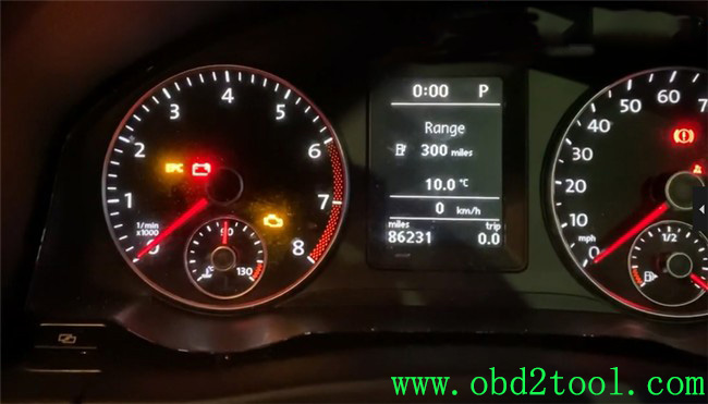
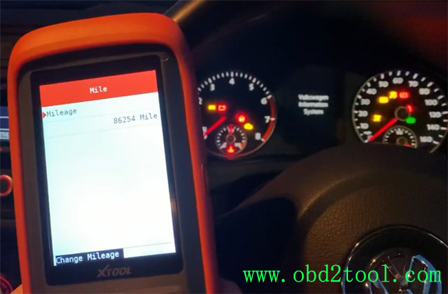
Connected X100 PRO2 to the OBD port of my car via the main cable. And turn the ignition switch on.
Now the mileage is 86231 now.
Then go to dashboard function, and select where the car was made not where you’re at.
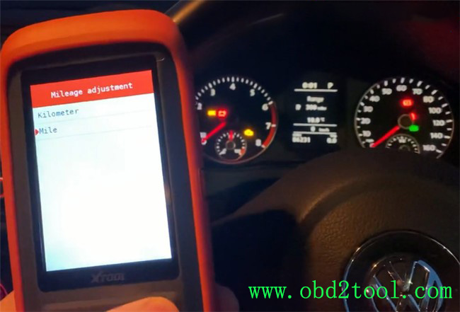
So I’m going to select Europe, VW, 2010 NEC+ 24C32 VDO, then select mileage adjustment and mile.
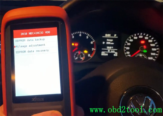
There is a note appears on the screen:
Before modifying mileage, make a backup of the EEPROM data.
Just read it and go to read the data.
It reads out the original mileage is 86254 mile. It’s a little different from the value on the dashboard, but it’s ok.
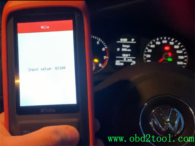
So I go to change mileage. Input the new value 82100 mile.
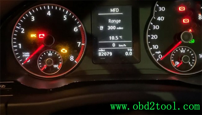
Awesome! The mileage is changed successfully, now the value on the dashboard is 82079 mile.
I’ve known some users say they cannot change mileage on their car with XTOOL X100 PRO2 auto key programmer. I don’t think it will work on all models, so it’s better to contact us before buying.
https://www.obd2tool.com/goods-10277-XTOOL-X100-Pro2-Auto-Key-Programmer.html
Posted by: Emily white at
09:16 AM
| No Comments
| Add Comment
Post contains 212 words, total size 5 kb.
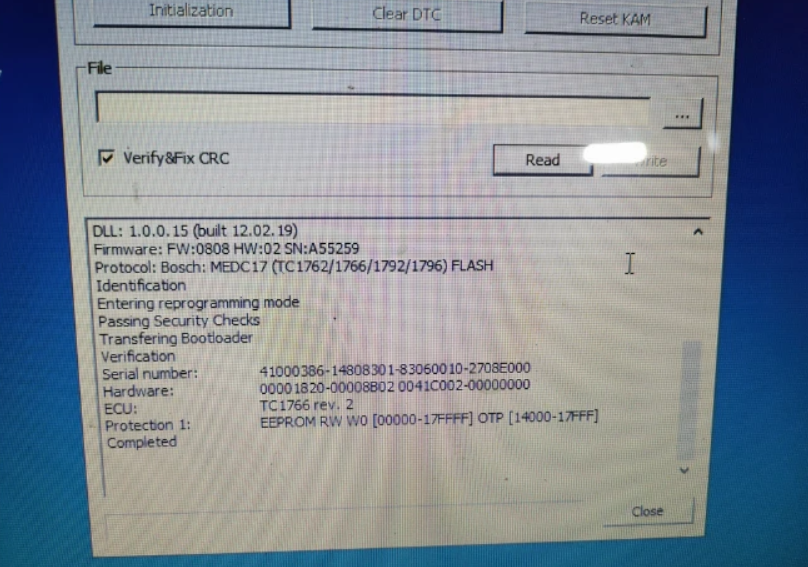
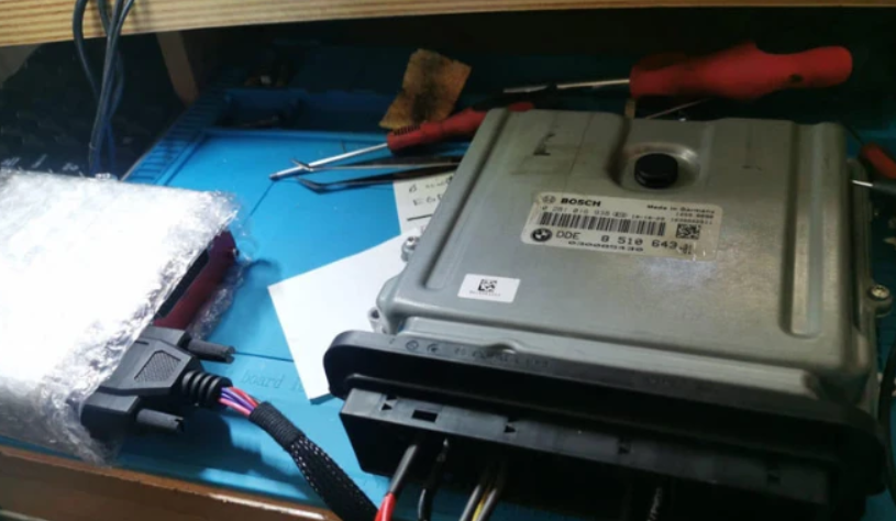
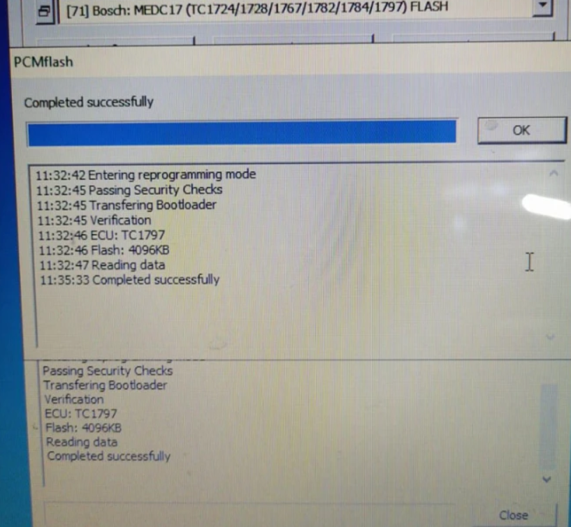
December 14, 2022
Caused the error reason:
Use other power supply notPCMtunerpackage plug will burn the resistance
If you use OBD for Power supply. Please do not plug in a sepatate 12v, otherwise, it will cause the device transistor or step-down chip to burn.
Must use PCMTuner professional power supply!
If you use your own lab power and viltage regulator.You don’t know how device power works.Just the voltage to 13.5 or whatever you think will cause the whole triode to turn out.
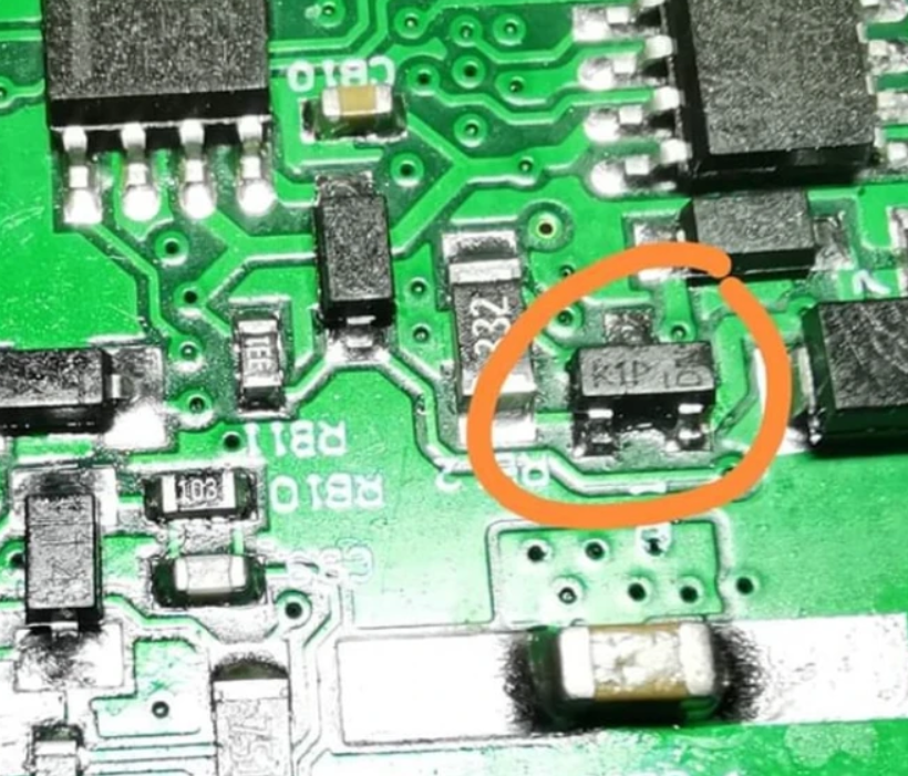
PCMTuner Module 71 Bench Mode Not Working solution:
1. Resoldered two resistance
2. Replace two resistance (if old resistance is lost or damaged)
Here is a resistance replace tutorials: Feedback by PCMtuner User:
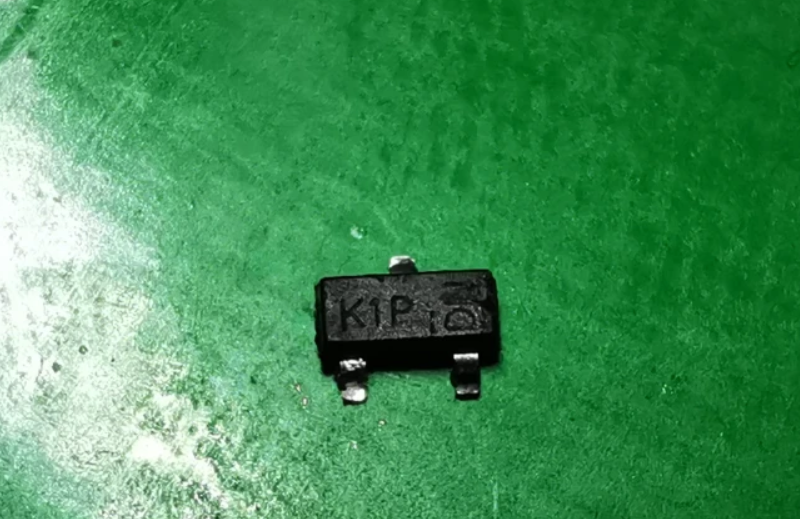
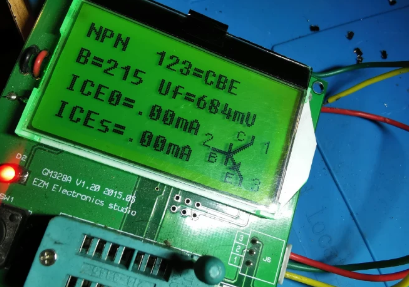
Resoldered two transistors K1P, and work bench mode. One Soldered K1P other analog p1P. I haved only one K1P
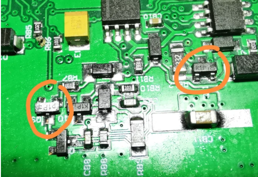
Replace first this transistor, K1P, analog 1P,p1P
K1p mmbt2222a-0.6A 40/75v and p1p pmbt222a – 0.8A 40/75V
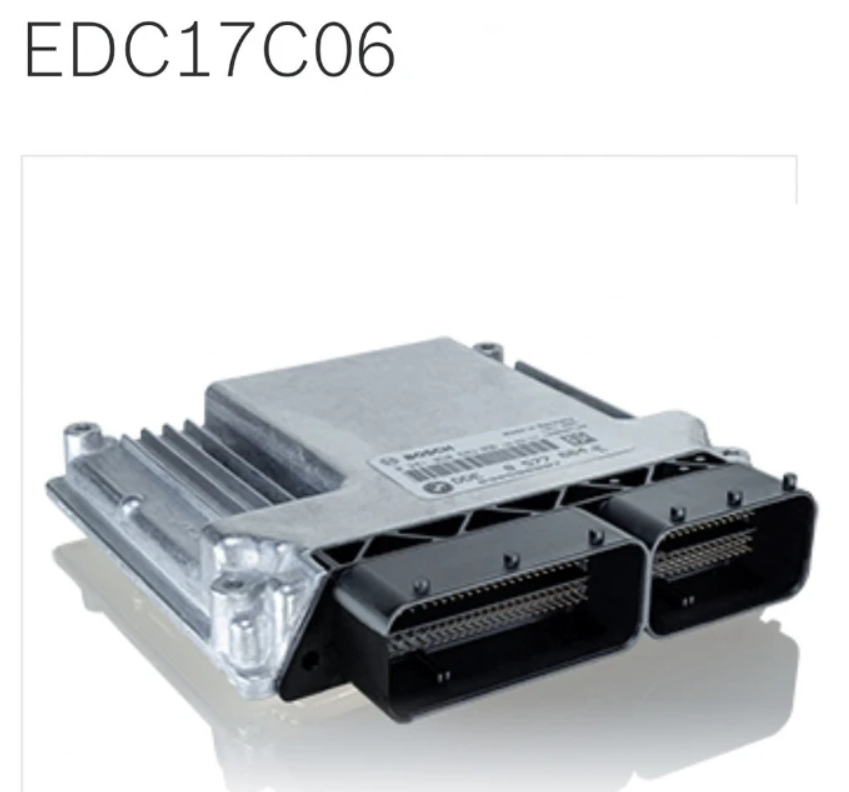
Read EDC17C06 on bench Successfully
Product Category: Engine Control Unit
Manufacturer Number: 0281015042
Brand: Bosch
Manufacturer:BMW
Vehicle Manufacturer No.:7811701
Posted by: Emily white at
01:36 AM
| No Comments
| Add Comment
Post contains 174 words, total size 6 kb.
May 22, 2022
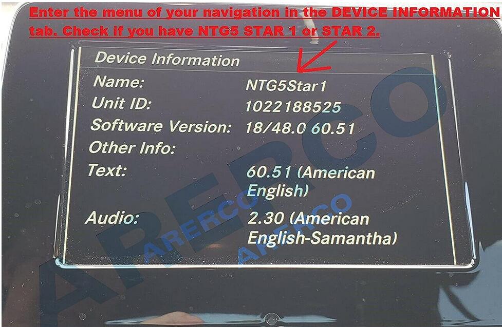
This instruction show you guide on how to update navigation for Mercedes Benz NTG 5 Star1 systems.
Navigation Map update SD Card works for Mercedes Navigation Garmin / Pilot.
Covers USA/Canada/Mexico/Puerto Rico/Virgin Islands/Bahamas.
PART #: A218 906 84 03 / A2189068403. VERSION 14.0 (MAP 14.0).
THIS CAN ONLY BE USED IN THE AUDIO 20 (Code 522) NTG5 Star1 Systems, see photos.
Please buy SD Card for Benz Navigation Update 2021 HERE on Amazon
Before payment please make sure you have an Audio 20(Code 522) NTG 5 Star1 systems.
Enter the menu of your navigation in the DEVICE Check if you have NTG5 STAR1 or STAR2.
The Star2 navigation looks the same as the Star1.
For Star2 model,SD card is difference an is NOT compatible with Star1.
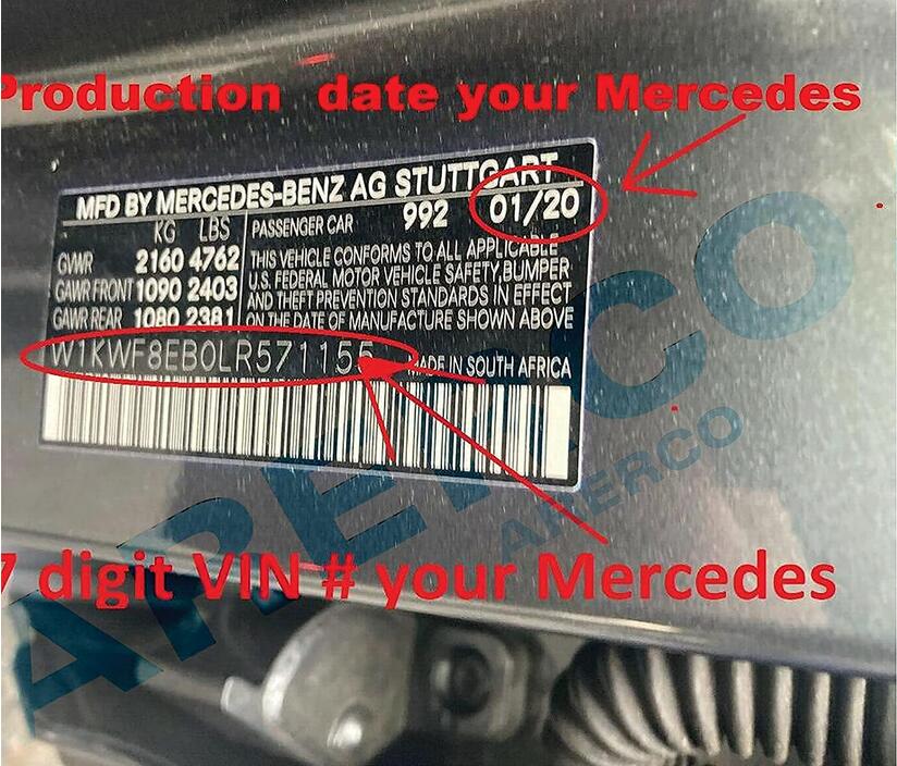
Check the production date of your Car.
Look on your 17-digits VIN stamp on the driver’s side door there will be a date printed on the upper.
COMPATIBILITY LIST:
Mercedes B-Class B250e-(build date on or after 12/2014-2019).
Mercedes CLA 250 / CLA 250 4MATIC / AMG CLA45-(build date on or after 12/2014-2019).
Mercedes CLS 400 / CLS 400 4MATIC / CLS 550 / CLS 550 4MATIC (build date on or after 09/2014-02/201![]() .
.
Mercedes C-Class C200 / C250 / C300 / C350e / C400-(build date on or after 08/2017-05/201![]() .
.
Mercedes C-Class C450 AMG-(build date on or after 08/2017-05/201![]()
Mercedes AMG C43 / AMG C63 / AMG 63 S-(ONLY 201![]() .
.
Mercedes GLC 300 / GLC 300 4MATIC / AMG GLC 43-(ONLY 201![]() .
.
Mercedes GLC 300 4MATIC Coupe / AMG GLC 43 Coupe (build date 08/2017-2019).
Mercedes AMG CLS63 S-(2015-2020).
Mercedes E-Class E250 / E350 / E400-(2015-2016).
Mercedes AMG E63 / AMG E63 S-(2015-2016).
Mercedes E400 / E550 Coupe-(2015-2016).
Mercedes E400 Cabriolet/ E550 Cabriolet-(2015-2016).
Mercedes GLA 250 / GLA 250 4MATIC / AMG GLA 45-(2016-2019).
Mercedes SLC 300 Roadster / AMG SLC43 Roadster-(2017-2019).
2018 Models ONLY work with vehicles built on/or AFTER 8/2017.
GLC’s MANUFACTURED BEFORE 8/2017 REQUIRE # A2139069903 SD CARD.
A2189068403-DOES NOT WORK WITH WIDESCREEN 10.25″ C-Class Models.
C-CLASS MANUFACTURED BEFORE 8/2017 REQUIRE # A2139069903 SD CARD.
C-CLASS MANUFACTURED ON/OR AFTER 07/2018 REQUIRE # A2139069807 SD CARD.
SD card can be used only in one vehicle.SD card will be locked with cars VIN.
Procedures:
1.Turn vehicle off
2.Locate the SD card slot.SD card slot is usually inside the center of armrest,or it is in the dash.
Consult your owner’s manual for assistance if needed.
3.Remove the old SD card.Your SD card slot is spring-loaded.
To remove the SD card just push the card in and release it.Do not attempt to pull the card to remove it without pushing it in first,as this could cause damage.
4.Insert the new Navigation SD card into the SD card slot until it clicks.
5.Start the engine.Press NAVI to access Navigation function.
When screen shows "ACTIVATING NAVIGATION,PLEASE WAITâ€.
It is pairing the card to the Car,after confirming "YES,THIS IS INTENDED VEHICLEâ€
SD card belongs to this car and card cannot be used with any other vehicle.
More information for Benz trouble repair,please refer to Mercedes Benz Trouble Repair.
Posted by: Emily white at
07:12 AM
| No Comments
| Add Comment
Post contains 519 words, total size 4 kb.
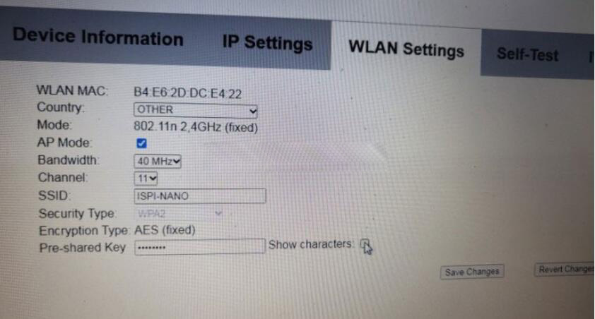
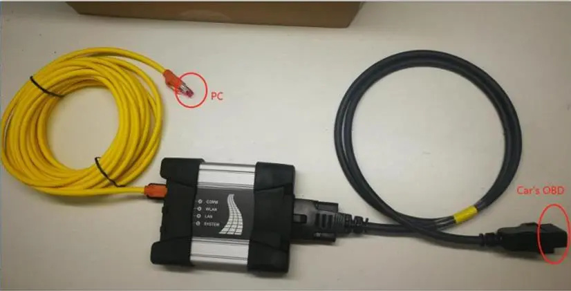
ICOM Next Wireless diagnostic
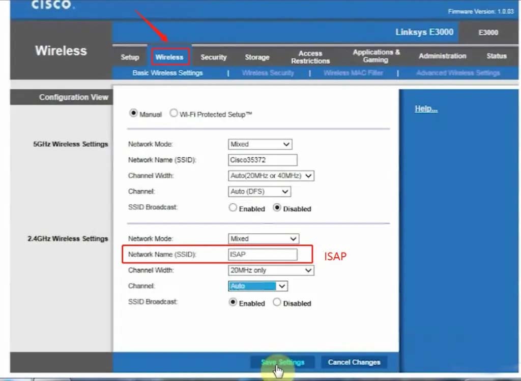
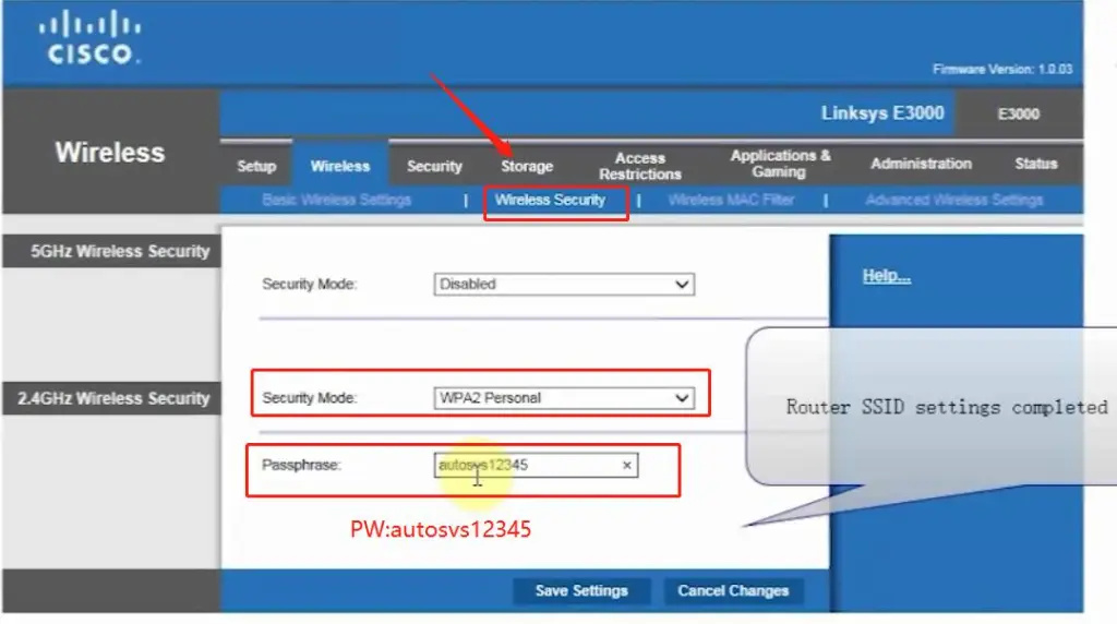
1.Set router wireless, wireless SSID name:ISAP,password:autosvs12345
2.Set ICOM NEXT A wireless, connected to the router,
wireless SSID name:ISAP,password:autosvs12345,
(Same as router setting, After setting the ICOM NEXT need to reconnect to vehicle)
3.BMW diagnostic PC connect to wireless router ISAP, you can start wireless diagnosis.
1.Configuration router
2.Configuration ICOM NEXT A
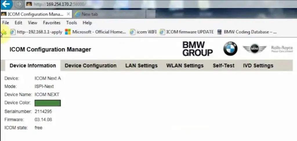
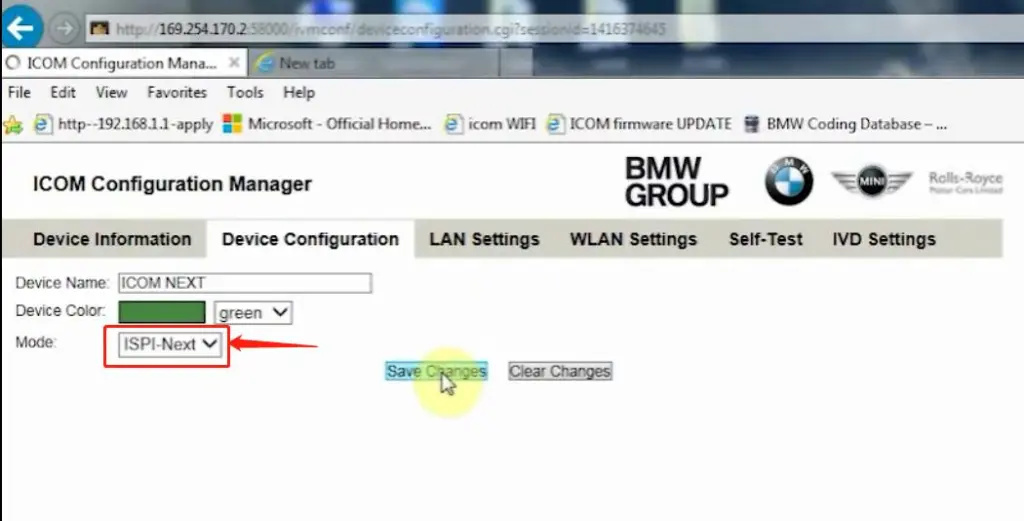
3.Same as the router configuration;
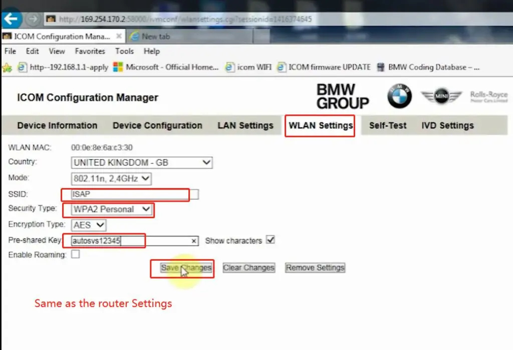
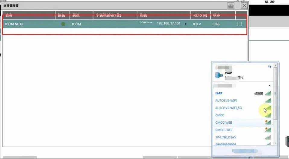
4.After ICOM NEXT configuration is completed, you need to reconnect, ICOM NEXT will automatically open the WLAN connection function;
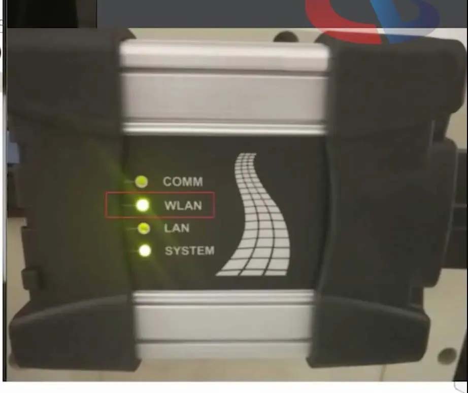
5.Connect ISAP WIFI;
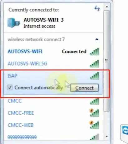
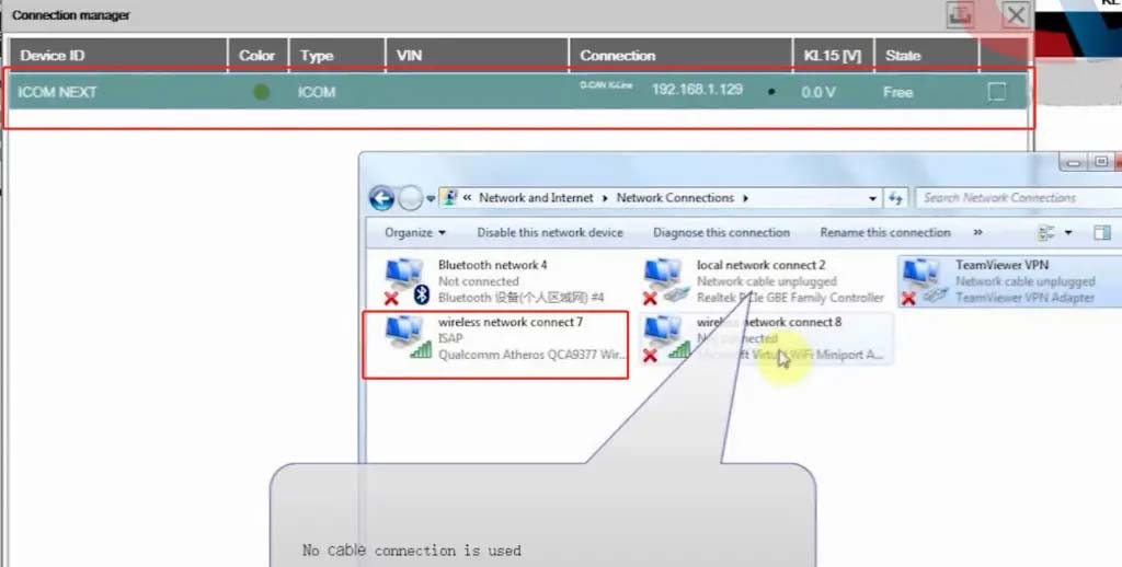
6.After the ISAP WIFI connection is successful, you can use the ISTA diagnostic test
Posted by: Emily white at
06:56 AM
| No Comments
| Add Comment
Post contains 104 words, total size 5 kb.
32 queries taking 0.2937 seconds, 196 records returned.
Powered by Minx 1.1.6c-pink.

